
Inner Geometry and Straightness of Pipes
Circular Triangulation Sensor “CiTriS”
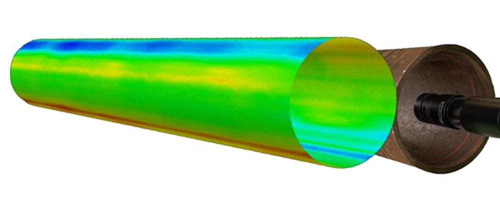
Using the Circular Triangulation Sensor from GL Control GmbH, the inner geometry of tubes, pipes, tanks and other cavities can be measured. The radial laser beam measures the inner geometry around 360° in 3600 angle steps. The result is a precise inner cross section, and a 3D model of the inner surface profile can be generated from the data obtained. Using this technology, the verification of tolerances is easy.
The sensor, which has no rotating parts, projects a 360° radial laser beam on the target inner surface and measures the contour. The projected laser line is imaged by a high-resolution image sensor. Using image analysis, the 2D contour of the cross section is created. In a single scan 3600 radii along the circumference are measured with a speed of up to 60 scans per second. The resultant radial resolution is 10 µm.
Operating at 60 scans per second, a 10 m pipe can be inspected in 180 seconds with over 10,000 cross sections. More than 38 million measurement points provide a detailed surface inspection.
Depth determination
To correlate the measured cross sections with the axial position of the scanner inside the pipe, a distance signal is used to trigger sensor measurements. The distance signal can be produced by an encoder. Each movement of the sensor will trigger a cross-sectional measurement. The integration of the encoder with the scanner is dependent upon the deployment method of the scanner. When mounting the CiTriS on a roller skid, the encoder can be mounted on a measuring wheel. In the case of small-bore holes and operation with sliding sleeves, the cable length inserted into the bore hole will be measured for information on distance. A special cable guide with integrated encoder is available. In the case of mounting the CiTriS on a lance, which is inserted into the bore, the encoder will be mounted directly on the lance guide.
3D measurement
By using this information, software can assemble all cross sections with precise depth information to create a point cloud of the inner surface of the pipe. The result is a complete 3D model of the pipe. The complete model can be dimensioned and analysed, with the ability to highlight and dimension defects. For the application of third-party external 3D analysis software, STL export is available.
Straightness determination
To determine the straightness of a pipe, an additional point laser is radiated through the pipe from the opposite opening as a benchmark. CiTriS will be guided slidable and approximately centrical, e.g. mounted on a roller carriage, into the bore opening. A module consisting of a camera and a focusing screen is attached to the front of the CiTriS to detect the directional laser.
The laser beam serves as an absolutely straight reference line. The detection unit is moved along this reference line in the pipe. Here, the offset to the reference line is continuously measured by the local detection of the laser point on the screen. A possible displacement of the detection unit from the center of the bore hole can be corrected using the measurement values from CiTriS.
The result provides the offset of the center point of the respective tube cross-section to the reference line at each measurement position. This corresponds to the straightness of the tube.