
Page 25 - ITAtube Journal 1 2019
P. 25
Technical Papers
Industrial experiment
Two billets of 190 mm diameter and four billets of 250 mm diameter on the TPA 70-270 (Fig. 4) were pierced according to the setup parameters presented in Table 1. In order to adjust these parameters, the outside diameter (fig. 4, d) and the wall thickness (table 2) of the hot shell were measured every time after piercing the next billet on the run-out table of the stand. The measurements were made by a vernier caliper on the head part of the shell at about 500 mm from the butt.
The final dimensions (diameter, and wall thickness) of all 6 pipes after sizing and cooling were measured on the examination table in 3 cross-sections (head, middle, tail) along the length of the tube. The meas- urements were made in two perpendicular directions. Results are presented in Table 2.
To assess the thickness variations of the obtained pipes throughout its length, diameters and wall thickness of two rolled workpieces (one for each size) were measured on the examination table at 9 or 10 cross-sections separated by 0.5 m (Fig. 4, c) after the shells had been sized and cooled. The diameter was an average of two perpendicular directions and the wall thickness — of four. The thickness in this case was measured by an ultrasonic thickness gauge. The results on thickness variations are presented in Fig. 5 (discussed later).
Analysis of the results
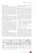
Measured values of the outer diameter and the wall thickness of the tubes (Table 3) agree well with pre- dictions obtained with QForm software. The relative errors of the outer diameter and the wall thickness do not exceed 1.5 % and 2.9 % respectively. It should
be noted that the estimated shell thickness is always a bit thinner than the actual one.
The lengthwise average wall thickness variations of the experimental pipes ø 200 x 31 and ø 270 x 44.7 came to 1.5 and 3.8 mm, respectively. For the pipe ø 200 x 31.8, these values do not exceed the estab- lished tolerances, although in some cross-sections of the pipe, they are significantly high (Figure 5). Rather, for the ø 270 x 44.7 tube, the average wall thickness variation exceeds the permissible limit.
The value of wall thickness variation estimated by the results of calculations using the computer model is approximately 1.5–2.0 times lower than the actual values (Figure 5). This can be explained by idealiza- tions inherent in the computer models. Such condi- tions include:
1. An ideal geometrical shape of workpiece and tools. While the actual production tools would exhibit wear, elastic deformation, and tool back- lash, these are not considered in the model;
2. Stability of the friction coefficient;
3. Assumed uniform heating up to the given tem- perature;
4. Isotropic mechanical properties.
An important factor is also the relative positioning of the tools and the workpiece in the deformation zone (rolls, guide shoes, plug). Linear position- ing errors may be of the order of a millimetre. It should be added that significantly lower vibration amplitudes of interacting bodies and, consequently, reduced forecast values of shape problems like wavi- ness and thickness variations are expected during the simulation process. In actual practice, the position
Table 3. Comparison of the computed and experimental results
ITAtube Journal No1/February 2019
25
