
Page 23 - ITAtube Journal 1 2019
P. 23
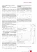
1 pusher; 2 workpiece (billet); 3 entry guide; 4 working rolls;
5 guide shoes; 6 plug rod; 7 plug; 8 box for refining the FE mesh
The workpiece material C45 (plain carbon steel C 0.45 wt %) was selected from the QForm database of deformable materials. An isotropic hardening model was used for simulating the plasticity of the work- piece. The contact friction between the workpiece and tools is taken into account by the Coulomb law. The “pusher” moves towards the main tools at a con- stant speed that is apparently lower than the rolling speed of the shell and is used for initially pushing the workpiece into the rolls. Thus the “pusher” action terminates as soon as the workpiece head is captured (gripped) by the working rolls. A forced surface mesh refinement on the workpiece and the tools has been implemented in the deformation zone, which con- tributes to a more accurate solution of the contact problem. The size of surface FE was no more than 7 mm for simulations described below.
The following assumptions have been made for sim- ulation purposes:
The tools were assumed to be rigid;
Friction coefficient is isotropic and constant throughout the entire simulation process;
Heat transfer between the workpiece and tool does occur; however, it is significantly simplified (thermal conductivity takes place only in a thin layer of the workpiece — a few transverse ele- ments’ size thick).
Preliminary calculations of two pipe sizes have been performed: ø 270 x 44.7 mm (diameter x wall thick- ness) from the round billet of ø 250 x 2800 mm (diameter x length, for a total mass of 1080 kg) and ø 200 x 31.8 mm from the round billet of ø 190 x 2850 mm (657 kg).
The simulation was conducted in order to determine the piercing mill deformation zone settings (distance between pairs of rolls and guide shoes, the front dis- tance of the plug, rotation speed of the rolls), that would provide satisfactory values of outer diameter and wall thickness of the finished tube in a single pass. The limit deviation for the outer pipe diameter is ± 1 % of the nominal value, for the wall thickness is ± 10 %. Variations in wall thickness of the pipe should not exceed 3 mm (variations in wall thick- ness is the difference between the maximum and
minimum wall thickness in the same cross-section of the pipe).
The outer diameter of the simulated rolled shells was chosen so as to take into account their subsequent reduction in the sizing stand and thermal shrink- age due to cooling. To obtain the predefined outer dimension of the virtual shell, the location of the tools has been adjusted in the same manner as if it were done in the real stand.
Calculation time for simulation of a piercing pass came to 33–35 hours for a billet originally 600 mm long.
The setup parameters for piercing these billets by only one pass in contrast to normal two passes (piercing itself and kind of reeling) were determined. Use of a single pass saves machine time, increasing productivity and reducing production costs providing that the geometry of the obtained shells is satisfac- tory.
Technical Papers
Table 1. Configuration parameters of the model for rolling experimental pipes
ITAtube Journal No1/February 2019
23
