
Page 21 - ITAtube Journal 1 2019
P. 21
Technical Papers
At the second stage, additional material properties and parameters that define the forming process are input. These include boundary condi- tions and initial conditions such as temperatures and velocities. Once all of the information has been supplied, the analysis can be launched. During the simulation, the computer solves a system of partial differ- ential equations that simulate a plasticity problem.
In the last stage the model predictions are examined using the post-pro- cessor. Typical parameters to be observed include:
1. contact areas,
2. stress and strain tensors,
3. velocity fields for deformable materials,
4. temperature of the workpiece and/or tools,
5. tool reaction forces,
6. the final workpiece shape,
The post-processor can also be used to identify any reasons for failure of the calculation (if applicable).
For simulations of the piercing process in cross rolls, the calculation results of interest include:
1. geometric parameters of shells,
2. helicoid line steps on the outer workpiece surface,
3. piercing machine time,
4. twist of the billet in the roll gap, and
5. predictions of surface waviness.
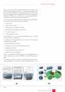
Figure. 1. a) Preparation of 3D models of tools in the CAD system; b) Finite element mesh generation, building up the deforming zone in QForm
The computer model of the piercing stand «TPA 70–270» was built for simulation purposes. This stand is located in JSC VMZ shop No 3, and is
Figure 1.
ITAtube Journal No1/February 2019
21
